
Page 3.
Building the
new Cab.
Update.
February
12, 2008.
While the axels
are underway, I started work on the cab.
As I said, I originally
ordered the "steel cab" version because the door placement matched No.
9.
"as built" (even
thought No. 9 "as built" had a wood cab)
I was going to
convert the steel cab into a wood cab, but keep the overall layout of the
cab the same.
But upon taking
a closer look at the cab, it wont quite work for this project. the rivits
are easy enough to take
care of, just
sand them off...but the curve of the roof is wrong, and the cab sides are
too short.
So I thought
it would be better to just scratchbuild a new cab..

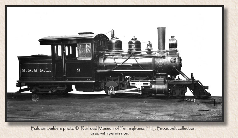
The prototype
drawing im using for the cab, and for this whole project, is from the
"Maine 2-foot
Cyclopedia Plan Book", published by Maine
2-foot Quarterly.
Part of the drawing
is visable in the photo above.
Its an actual
Baldwin drawing! extremely accurate. I was using the Crittenden drawing,
but it shows
the "late" configuration of No. 9, with the new steel cab and the replacement
tank.
The M2FQ plan
book drawing shows No. 9 "as built"..which is what im building.
Update.
March
3, 2008.
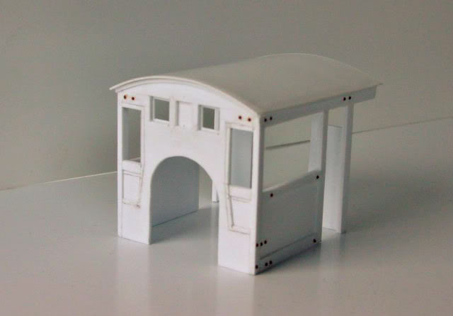
The cab is about
75% complete..still needs a roof, some rivits,
two windows and
two doors.


Update.
March
16, 2008.
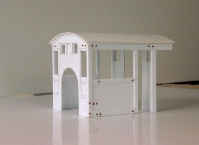
The cab is complete! 
(well..not completely..it
still needs windows, doors and more rivits..but its "complete enough" that
im ready
to set it aside
and move on.)
Here are some
pics of the new cab, and compared with the Bachmannn forney cab.
you can see the
difference in the roof curve, and other detail differences.


I also modified
the tender tank..and discovered something interesting..
Bachmann made
a mistake!
Its not a huge
deal, and most people probably won't care, won't notice, or even be aware
that its wrong,
but it is
wrong, and I had to fix it! 
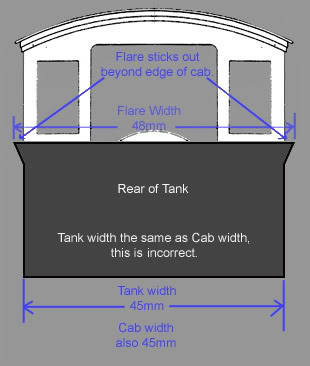
The Bachmann forney
has the width of the cab, and the width of the tender tank the same.
and the tank
flare sticks out beyond the edge of the cab sides..this is historically
incorrect.
first, some terms
to help explain..
"cab width"
"tank width"
"flare width"
Cab width is simple..its
the overall width of the cab:
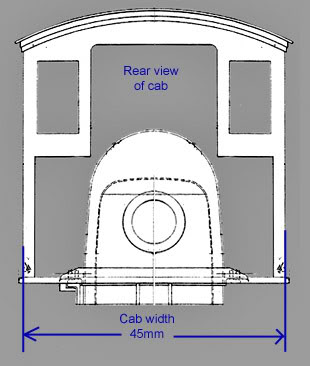
On the Bachmann
forney, (and my new No. 9 cab) the overall cab width is 45mm.
this is fine,
correct and not the problem..
the problem is
the tender tank.
On the Bachmann
forney, the "tank width" is also 45mm, matching the width of the cab,
so that the cab
sides and tank sides are flush and even with each other,
and the overall
"flare width" is 48mm, so that the flare sticks out beyond the edge of
the cab..
this is incorrect:
and a photo of
the Bachmann forney:

That is simply
wrong..no Maine forney was built that way.
(or ANY forney,
as far as I can tell so far..)
Instead, the "flare
width" should be 45mm, matching the cab width,
and the "tank
width" is narrower than the "cab width", and the tank side sits inside
of the cab sides,
like this:

I looked through
EVERY Maine 2-footer book I own..
you can do the
same to confirm this!
EVERY photo of
every Maine 2-foot forney (with a flared tender)
shows this Cab/Tank
relationship.
The flare is
always flush with the cab.,,the flare does not "stick out" beyond the edge
of the cab.
The only exceptions
I could find to this are modern photos of Monson 3 and 4, and WW&F
#10.
Current photos
of those three locos show the "flare" being wider than the cab.
(All three happen
to be built by Vulcan)
so at first I
thought maybe Vulcan was the exception, and they built forneys with the
flare
extending out
beyond the cab..but this is not the case either, because the builders photo
of WW&F number
10:
http://www.ironhorse129.com/Prototype/SteamClass2004/Vulcan/vulcan_574.jpg
also shows
that "flare width" and "cab width" are the same, and the tank is narrower.
so Vulcan also
built them this way..
The current tanks
on Monson 3 and 4, and WW&F 10 are rebuilt or replaced tanks,
not the originals.
So Bachmann simply
got it wrong..
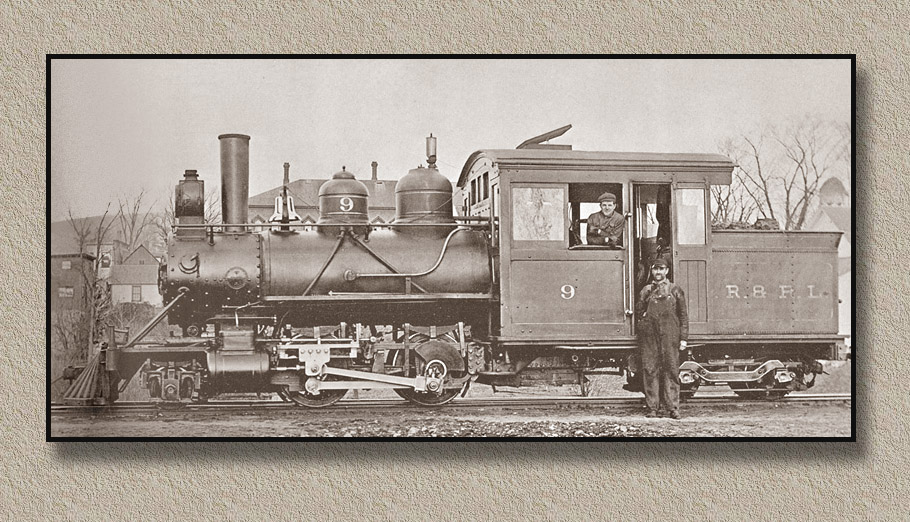
Every historic
photo of a Forney I can find, (even Mason Bogies) shows the "flare" being
flush with the
cab side, and not extending beyond it.
Here is one example:
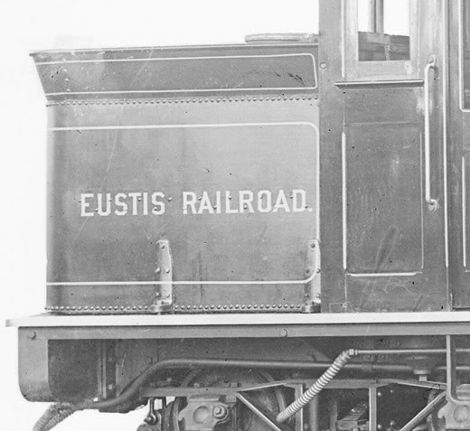
Most photos of
locomotives are taken from a front angle, so the cab/tank division is
hard to notice.
Above is a detail from the Baldwin builders photo for Eustis number 8.
notice the top
of the flare is even with the cab, and the edge of the cab partially hides
the tender
bracket.
The builders photo
of SR&RL 9 and WW&F 7 also show this clearly.
Since the majority
of loco photos are front-angle views, its hard to find good examples that
show it
clearly, but
take a look through your books, you can find many more examples.
The locomotives
with "non-flared" tenders, such as SR&RL 10, B&H 7 and B&H
8, and others,
do have the tank
width and the cab width the same..with no tender flare.
Everything above
applies to "flared" tender tanks only.
So I went ahead
and modified the Bachmann tank, removing 3mm from the width, making the
"flare width"
45mm, the same
as the cab width.
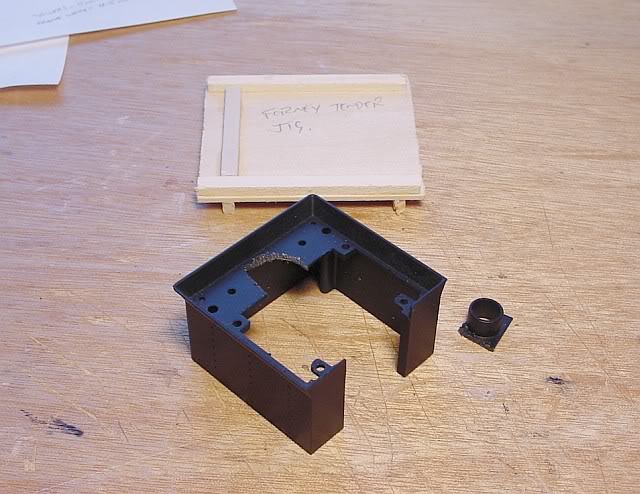
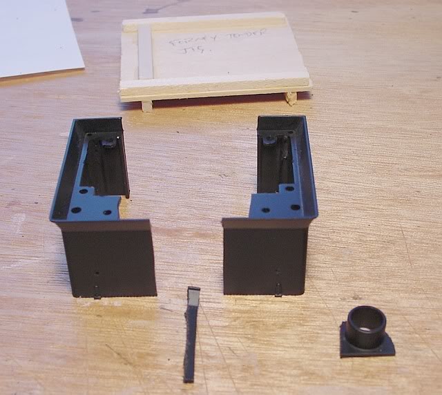
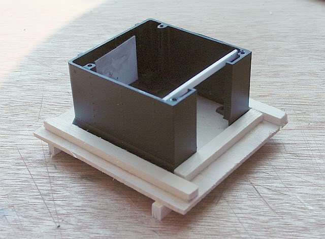
I made a simple
jig out of wood..the distance between the sides is 45mm, I used the jig
to glue the tank
back together. some squadron putty to fill in the gaps, and the tank is
done.
This narrowing
of the tank did cause some problems with the electronics that sit inside
the tender,
they no longer
fit! I had to unscrew the circuit boards from their mounts, cut the mounts
off,
and insert the
circuit boards into the tender at an angle..they still fit, barely.
And thats it for
the cab and tank!
(as I said, the
cab still needs a few more details..I will add those later)
Next up, grinding
away at the frame! 
coming soon...
 To
Page 4, Frame regauged! To
Page 4, Frame regauged!
 Back
to Page 1 of SR&RL No.9 Back
to Page 1 of SR&RL No.9
Back
to my main page.
|
